In-Plant Training for CNC positions

Laser calibration of a machine tool hardly proceeds at light speed. For example, bi-directional laser calibration of just one 40-inch axis of a CNC mill might take the better part of an hour, with the machine axis moving in 10-mm increments and stopping to settle as the laser interferometer takes each reading. That pause for each reading can be as long as 23 seconds, says Renishaw, a supplier of machine calibration technology including laser systems. The cumulative effect of all of these little waits can translate to considerable downtime for calibrating a large, high-value machine tool. In some cases,—depending on machine crashes and the shop’s quality system, the company says—a critical machine might be out of action for several days per year just for this calibration. Owners of these machines are obviously very aware of the lost production.

But there is a solution, Renishaw says. A technique taking advantage of a feature in its XL80 laser interferometer reduces the settling time to just 250 milliseconds after each incremental axis move, cutting calibration time by 85 to 95 percent. In addition to returning the machine to production more quickly, this technique also better reflects axis positioning accuracy under real cutting conditions, because in real cutting, the moves are fast and the settling time is slight before the tool engages the work.

Quality Tech Services of Byron, Georgia, uses this time-saving technique with the XL80. The company has instructed new laser buyers on using it as well. Company owner Mike Schraufnagel says, “As a calibration service, the first concern we hear when we walk in the door is downtime on a machine. Customers will do anything to cut downtime on a critical asset.” His customers who own lasers themselves have employed this technique to keep their Cemented Carbide Inserts machines cutting, while his own team uses it to increase its overall efficiency. “What normally would take 30 minutes now takes just 3,” he says. “In one afternoon, we were able to complete six laser setups and three ballbar setups on a machine in 2 hours.” In the past, this work would have taken at least a day.

An M code and an open contact relay are the prerequisites that make this technique possible. To achieve the high speed calibration, the machine’s CNC uses an available M code to close a “normally open” set of relay contacts for between 10 and 20 milliseconds. If the M code to effect this trigger is not available, it might be available for purchase or activation through the OEM. Closure of the relay contacts via an auxiliary I/O cable provides a trigger for the laser to record the difference between the measurement reading and the VCMT Insert target position.  

“We identified spare relays that can be controlled via M codes on a Haas CNC machine in our lab,” explains Michael Wilm, Renishaw’s calibration business manager. Using the relays to trigger the laser interferometer and thereby reduce machine downtime was the idea that developed from this discovery. The laser simply needs to see the relay close for as little as a microsecond, but mechanical relay contacts can bounce for the first few milliseconds, he says. Therefore, “we have added a bounce rejection feature programmed into the electronics of the laser. Any chatter within 20 milliseconds gets ignored, the laser takes a reading, and the axis moves to the next measuring position.” The result is laser calibration that proceeds quickly, and more like the way the machine will move during normal production. 

The Carbide Inserts Website: https://www.estoolcarbide.com/product/wnmg-carbide-inserts-for-stainless-steel-turning-inserts-p-1189/

CNC: Insert coatings and your shoe’s sole – what’s the connection ?

Every industry and application is different, but metal parts often look and feel superior to their plastic counterparts. Metal provides a gloss and sheen, as well as the appearance of strength and durability. Plastic is incredibly useful, but metal often wins in the overall quality stakes.

On the other hand, plastic parts are often much cheaper to make than metal ones. The raw material is often less expensive, and manufacturing processes like injection molding make it easy to fabricate thousands of plastic parts in a very short space of time, at little cost. Additionally, plastics are often much lighter than metals, making them indispensable in applications where a part must remain lightweight.

But what about situations in which Carbide Aluminum Inserts a part needs to combine the benefits of metal and plastic? What if a part needs to look like metal or behave like metal on the surface, but remain both lightweight and affordable? Fortunately, there are several smart processes we can use to make parts that are plastic on the inside and metal on the outside. It’s not magic, but it’s very, very useful.

These processes can be grouped under the general name of metallizing or metallization. During a metallizing process, a metal coating is applied to the surface of the part, giving it a new, metallic surface layer that can be aesthetic, functional or both.

Estoolcarbide has years of experience adding metal coatings to parts of all shapes and sizes. Prototype or end-use part, a well-applied metallized finish can be the difference between a successful part and an unsuccessful CNMG Insert one.

Why metallize a part?

There are many reasons why a company may want to add a metal coating to a part. These are some of them:

For starters, all metallizing processes are capable of radically altering the appearance of a part. A component made of colorless, matte ABS, for example, can be transformed into something sleek and glossy with a relatively inexpensive metallizing process. This is particularly useful for consumer products, where appearance is often as important as functionality.

Beyond aesthetics, metallizing can make a substantial difference to the functionality of a part. Because metals have different physical properties to plastics, a metal coating can have the effect of adding a protective layer to an otherwise vulnerable part. Metal coatings can be abrasion-resistant, making the metallizing process useful for parts that will have a physically demanding end use.

Another important property of metals is their ability to conduct electricity. By adding a metal coating to a plastic part, manufacturers can adjust the level of electrical conductivity a part for purposes like electromagnetic shielding. The process opens up new doors for engineers making electrical and mechanical components.

Benefits of metallizing:

  • Aesthetics
  • Protective layer
  • Functionality
  • Conductivity

Types of metallization

Metallizing is a general term used to describe different ways of applying metal to a non-metal part, and there are several vastly different processes one can use. At Estoolcarbide, we offer many surface finishing options for metallizing your parts, each of which has its own particular benefits.

Our metallization services include:

  • Vacuum Metallizing
  • Chroming
  • Chrome Sputtering
  • Color Plating
  • Zinc Plating
  • Tinning

Metal on metal?

While metallization is often used to add a metal coating to non-metal parts, it is also possible to coat a metal part with a different kind of metal. Again, this could be for aesthetic reasons, or to provide a part with a new function.

One of the most common methods for adding a metal coating to a part is plating. Plating is famously used to add a desirable surface finish to jewelry, but its uses go far beyond that. In fact, plating is a highly versatile process that can be used to adjust finish, function and conductivity of a metal part.

Need to add a metal coating to the surface of your part? Get in touch with Estoolcarbide to discuss metallization options, or browse our full range of surface finishing options for more ideas.

The Carbide Inserts Website: https://www.estoolcarbide.com/product/best-price-tungsten-carbide-inserts-from-china-turning-inserts-vnmg160404-tm-vnmg160408-tm-vnmg160412-tm-vnmg432/

Tips for Importing Carbide Cutting Tools from China

Carbide inserts are virtually certain to have been used at some stage in the careers of all those who have done work with machines that cut metal. Inserts made of carbide for cutting tools are a product that cannot be overlooked in the metal cutting tool sector. Boring, turning, cutting, drilling, grooving, hobbing, milling, and threading are just some of the many applications that make use of them.

Carbide gives materials a high hot hardness in addition to a remarkable wear resistance when used in their construction. Carbide inserts are a superior option than high-speed steel when it comes to durability, making them a good pick for use in applications that require cutting metal. Coatings that provide additional resistance to wear, such as titanium nitride (TiN), titanium carbonitride (TiCN), titanium aluminum nitride (TiAlN), and aluminum titanium nitride (AlTiN), may lengthen the life of inserts by a significant amount. Examples of these coatings include titanium nitride (TiN), titanium carbonitride (TiCN), titanium aluminium nitride

Carbide inserts are manufactured in a large number of distinct geometric forms, each of which is customised specifically to each certain application in order for them to be able to carry out the various cutting processes. Carbide inserts are used in a variety of industries, including automotive, aerospace, and construction.

Carbide is more brittle than other standard tool materials, making it more subject to chipping and breaking, in addition to being more costly per unit than other typical tool materials. Because of these drawbacks, the carbide cutting tip itself is sometimes designed in the form of a tiny insert that is intended to be used in conjunction with a larger cutting tip on a tool whose shank is constructed from a different material, most frequently carbon tool steel. This provides the advantage of employing carbide at the cutting interface without the high expense and brittleness that would be associated with manufacturing the complete tool out of carbide. Carbide inserts are used in the majority of contemporary face mills, in addition to numerous lathe tools and end mills.

Inserts that are round or circular may be used for button milling, in addition to turning and splitting radius grooves. This is because of their versatility. Copy cutters, which are often referred to as button mills, are machines that make use of circular inserts that have a radiuses edge to a significant degree. Because of this, better feed rates and deeper cuts may be performed while consuming a much reduced amount of electricity. The transformation of radial grooves into a round component is referred to as “radius groove turning,” and the method is named after the term. Parting is the process of cutting through a section in its entirety, and the term refers to both the procedure and the result.

When one of the insert’s cutting edges is worn, it may be turned to a fresh, unused edge for shapes that are triangular, square, rectangular, diamond, rhombic, pentagon, and octagon. Other shapes that have multiple cutting edges include octagon, pentagon, and rhombic. Other forms, such as rhombuses, pentagons, and octagons, also contain many angles that may be used for cutting. These inserts have a variety of applications, including turning, boring, drilling, and grooving, to name a few of them. You may get more use out of an insert by utilizing its worn edges for roughing applications before rotating it to a fresh edge and using it for final machining. This will allow you to get more life out of the insert.

Carbide insert wear that is visible in woodcutting is caused, in great part, by chemical corrosion with the cobalt binder of the carbide (glue). Because of this, the tough tungsten particles are able to leach away, which results in a blunting of the cutting edge.

Carbide CNC inserts Process:

  • Batching
  • The absolute best raw material consists of a very fine spherical powder formed of cobalt, in addition to other compounds that have an extremely high level of purity. It is possible for each batch of powder to preserve its homogeneity and consistency throughout the production process by using the most cutting-edge mixing and wet milling technologies, in conjunction with accurate calculation.

  • Ball Milling
  • The nanotubes are reduced to an extremely fine powder by a process known as ball milling, which is a kind of grinding. This operation is also known as milling. During the process of ball milling, a localised high pressure will be formed as a consequence of the collision between the tiny hard balls that are enclosed in a concealed container. This collision will take place within the mill.

  • Spray Drying
  • Utilizing a spiral spray dryer tower allows for the powder to have an exceptional fluidity, which, in turn, leads to a density that is consistent throughout the carbide inserts blanks. This is the end product of the process. Our fixed tower, which is only committed to defined tasks, avoids any mixing of grains of varied sizes within a batch. This helps to ensure that the uniformity and high quality of each and every substrat is maintained throughout the production process.

  • Pressing
  • To get started, the material is put through a press that is highly automated, CNC controlled, and equipped with punches and dies so that it may be pressed into the necessary basic shape and size. The inserts, after being pressed, have a look that is quite similar to that of a true carbide insert; nevertheless, their hardness is not even close to meeting the requirements. Imported press machines and high-precision moulding machines, along with homogeneous spray powder, ensure that the density of the substrate body is comparable with the density of the clearance as well as the cutting edge of carbide inserts. This is accomplished by ensuring that the density of the substrate body is the same as that of the clearance. The grind value is delicately adjusted so that the whole surface and cutting edge are constant, as well as the tool’s durability and duration of use. This is done so that the tool may be used for a longer period of time.

  • Sintering
  • In order to get the desired result of increased brittleness, the insert is subjected to a heat treatment that lasts for 15 hours and is carried out at a temperature of 1500 degrees Celsius. Sintering is the process by which the molten cobalt and tungsten carbide particles are brought together and bonded together. First, the insert goes through a significant shrinkage, and this shrinkage must be precise in order to achieve the appropriate tolerance; second, the powder mixture is transformed into a new metallic material that is known as cemented carbide. The treatment process that takes place in the sintering furnace accomplishes two goals. The cobalt magnetic pole tolerance on the inside of the sintering furnace is guaranteed carbide drilling inserts to be within 0.3, and the magnetic force is guaranteed to be within 0.5. Neither of these parameters may be outside of their respective ranges. Carbide inserts that are manufactured using a large number of batches have remarkable stability. This is because even the smallest amount of variation is sufficient to minimise the quality variation of each batch to a minimum as much as is humanly feasible.

    The following phase in the process, which comes after the insert has achieved the necessary amount of hardness, is to bring it to a point where it can be delivered to the customer. Before going on to the next step of manufacture, we will first use the coordinate measuring equipment to do a comprehensive check to confirm that the size of the insert satisfies all of the parameters. This will be done before we move on to the next stage.

  • Gross Inspection
  • When doing quality control on the raw materials, it is necessary to make use of a carbon-sulfur analyzer. This is done to ensure that the tungsten carbide powder has an adequate amount of both carbon and Sulphur.

    After the sintering process, the material is examined using a variety of tools, including the following: Conduct tests to determine the TRS of the carbide rod, as well as its microstructure, cobalt concentration, and the material’s hardness. Include a dropping test to confirm that there is no flaw in the material in the centre or inside of the blank. Additionally, include an ultrasonic scanner for carbide die blanks to check that there is no sand hole inside the blank.

    After being sintered, the material is subjected to a manual examination, which it must pass. Carburization and decarburization, sand holes in the surface, and tiny fissures are some of the things that should be looked for while doing a visual inspection of the material to determine whether or not it is flawed.

    After sintering, the sizes are checked using the following criteria: A micrometer will be used to measure the dimensions, and an additional test for roundness will be performed on carbide rods.

  • Grinding
  • Diamonds are used in the grinding process so that the carbide insert will ultimately have the correct shape after the operation is finished. In order for the inserts to be of a quality that is commensurate with the requirements imposed by the geometric angles, they are ground using a variety of techniques. Throughout the process of grinding, the insert is subjected to checks and measurements by the grinder’s built-in measuring control at a number of different places.

  • Semi-Inspection
  • After yet another visit to the lab for a quality check, the top and bottom of the insert are ground to the right thickness. This completes the manufacturing process. The stage that we are now at is called the semi-inspection. Grinding cemented carbide, which is the hardest material that humans have ever discovered, needs industrial diamond, which is the hardest mineral that exists on any planet.

  • Passivation
  • After the insert has had its thickness reduced to the proper level, it is subjected to further grinding in order to create the ideal form and dimensions for it. Higher standards, both in terms of performance and stability, have been imposed on cutting tools in order to meet the needs of contemporary high-speed cutting and automated machine tools. In particular, coated tools have to go through the process of passivation before they can be coated. This is done to guarantee that the coating will be durable and will last for a long time. The objective of the edge passivation technology is to solve the issue of the micro notch defect that is left on the edge of the carbide inserts after grinding, to reduce or eliminate the edge value, and to achieve the objective of making the edge smooth, sharp, and durable.

  • Cleaning
  • Once the inserts have been machined, the next step is for them to be cleaned, and then they are shipped to be coated. When working with the inserts at this stage, it is imperative that protective gloves be used so that no oil or dust gets on the hands. They are given a coating after first being positioned into fixtures that are fastened to a carousel and then being placed within an oven that maintains a low pressure. This is the component of the insert that is responsible for giving it its unique color.

  • Coating
  • Not only does it completely relieve the internal tension of the substrate, but it also removes the unevenly high edges of the carbide inserts, which means that the continuity and consistency of the edge of each carbide insert is substantially improved. The state-of-the-art sandblasting and grinding equipment that are equipped with the pre-coating treatment method that was created by our company make this accomplishment feasible.

    Chemical vapour deposition, often known as CVD, and physical vapour deposition are the names of the two methods that are used to coat objects in today’s world (PVD). The nature of the material and the processing procedure come into play when deciding which coating method to use. The thickness of the coating is going to be determined by the application of the insert, and the thickness of the coating is going to have an effect on the durability and the life of the insert. The surface of the cemented carbide is coated with a number of very thin coatings, including as titanium carbide, aluminum oxide, and titanium nitride. These coatings have the potential to considerably prolong the material’s service life and durability. The fact that there are a lot of coatings is the closely guarded technical secret behind this.

    Before adding gaseous chloride and oxide, as well as methane and hydrogen, the insert has to be positioned within the furnace in the event that the coating procedure involves the CVD approach. These gases interact with one another and also take action on the surface of the cemented carbide to generate the insert when the temperature reaches one thousand degrees Celsius. You will wind up with an even coating that is no thicker than a few thousandths of a millimeter at most. This will be the result of your efforts. The value of some coated inserts goes up because the surface is given a golden finish. In addition, the lifespan of the coated inserts is much longer than that of the untreated inserts by a factor of five. PVD is sprayed onto the insert while it is heated at a temperature of 400 degrees Celsius.

  • Inspection
  • Following the completion of the final inspection, each insert is checked against the blueprints and the batch order to ensure that it meets the standards. After that, you may finally start packing it. After having the proper grade laser-etched into the insert, it is then placed in a grey box that has a printed label affixed to it. Finally, the insert is given its final presentation. It is now ready to be distributed to the many customers who purchased it. On the insert box, you’ll find not only information about the product, but also the date, as well as the serial number.

    Why Carbide Inserts Are So Great?

    • When compared to other types of tools, carbide inserts provide superior levels of productivity and cost effectiveness.
    • Carbide is a particularly durable substance, which results in a significantly increased amount of time-spent working.
    • Tungsten carbide is available in more than a dozen distinct grades, and each of these grades has the potential to be used for a variety of purposes.
    • Carbide materials, when used as cutting tools, give a surface finish quality that is much superior to that of other materials.

    In addition, carbide recycling materials such as carbide inserts may be used to a wide variety of purposes, which makes these materials an important component for a lot of different companies. Let’s take a more in-depth look, shall we?

    • Surgical Instruments

    Tungsten carbide is one of the most often used instruments because it is both precise and long-lasting, two qualities that are essential for a variety of medical operations. One of the most noteworthy applications for carbide is in surgical instruments. Tungsten carbide is used to manufacture the tip of the blade of the tool as well as the end of the utensil, despite the fact that the base of the tool itself is normally fashioned from titanium or stainless steel.

    • Jewelry

    Carbide is an excellent material for jewelers all over the world to use, not just for the shape of jewelry but also for the jeweler itself. Tungsten is an excellent material for wedding rings and other types of jeweler because of its high level of hardness, which places it just slightly below that of diamonds. In addition, jewelers have to depend on effective tools in order to work on these items, and carbide is an excellent material for that purpose. What’s not to like about tungsten jeweler, since it has a great appearance, is highly durable, and is often less expensive than gold?

    • Nuclear Science

    Carbide has also shown to be an efficient neutron reflector in several applications. This robust substance was also employed during the early research into nuclear chain reactions, notably for the protection of weapons during those early studies. Although the usage of carbide in this business is not quite as prevalent as it may be in some of the others, it is very essential that anybody working with any kind of material do so in the most careful manner possible..

    Conclusion

    The insert grade that you employ may make all the difference in the world when it comes to how productive your manufacturing process is, and this is true regardless of the size, material, or design of the component. You may keep ahead of the competition by choosing the appropriate insert for the particular machining process you will be doing. Inserts are an essential part of the metal cutting process and cannot be imagined without them. The inserts themselves are crafted from some of the most abrasive substances that can be found anywhere in the globe.

    Carbide inserts manufacturers like HUANA are able to fulfil the demands for ever-increasing feeds and speeds, as well as the need for longer tool life and reduced costs, by continuously refining the designs of tungsten carbide inserts and creating better and better coating methods. As one of the leading manufacturers of carbide inserts, HUANA offers the best cutting tool solution for almost any application or machining process. With a variety of inserts and insert configurations that have been designed specifically for different metals, such as steels, stainless steel, cast iron, and aluminum alloy, HUANA is able to cater to a wide range of cutting needs. Whether you are roughing, grooving, finishing, or doing any of the various forms of machining. Due to the extensive variety of carbide insert goods and solutions that we provide, we are certain that you will find exactly what you are looking for.

    The Carbide Inserts Website: https://www.estoolcarbide.com/product/dnmg-carbide-inserts-for-stainless-steel-turning-inserts-p-1185/

    Lathe Cutting Tools: Different Types of Tools for Turning

    Injection molding is one of the most popular methods for rapid manufacturing. The injection molding draft angle is a critical parameter in this process that has a significant impact on product quality.

    In this article, our discussion will focus on draft angle injection molding. We will explain what is draft angle, why it is important, and what things you should keep in mind while designing molds for injection molding.

    The injection molding draft angle is an essential geometric feature built into molds for injection molding. It is the taper, or degree of inclination, of the mold’s walls along the drawing direction.

    As it is a feature of the mold, the draft angle is also visible on the component. Its unit of measurement is degrees.

    Typically, engineers use an angle of around 1.5 degrees. However, it can range anywhere between 0.5-10 degrees for certain special applications.

    It is easy to grasp the concept of what is the draft angle. Its benefits, however, are not as intuitive to understand and require some discussion. It is the most important among all molding angles. Small miscalculations can ruin the entire product line and even damage the injection molding equipment.

    Without further ado, let us dive into the various reasons that make it an important injection molding parameter.

    Part ejection is a crucial carbide turning inserts step in the molding process and a major reason for having the injection molding draft angle. Right before part ejection, the part is in contact with the walls of the mold. The contact stresses are high enough to deform the part from friction during ejection.

    Therefore, it is desirable to minimize the impact of this frictional force. Engineers do this by including a draft in the mold. As soon as the part is pushed outwards by the ejector pins, the entire part pops out and loses contact with the mold walls. This lack of contact translates to no friction.

    Without the draft angle, the part would rub against the surface of the mold throughout the ejection process, as seen in the figure. This is highly detrimental to the surface finish and manufacturing tolerance.

    Moreover, the lack of friction also decreases the required ejection force, positively impacting the power requirements and also speeding up the ejection process.

    Warping is one of the serious defects in injection molding processes. To explain what it is, refer to the figure in the previous section showing parts with and without draft angles.

    When there is no draft angle by design, a vacuum might form in the empty space that appears when the part is ejecting. This vacuum causes the part to fold in on itself. This undesirable deformation is warping.

    As can be seen, this issue is not present with an injection molding draft angle. As soon as the ejection process begins, the part separates from the mold and creates room for air to fill all cavities, preventing the vacuum from forming. Therefore, no warping occurs.

    We briefly touched upon this advantage of draft angle injection molding in the previous section. Due to the draft, the part does not rub against the mold, which preserves the surface quality.

    An important consideration here is the variation of the draft angle with the surface texture requirements. The draft angle needs to accommodate surface texture features as well in addition to the gross geometric features of the component.

    This means that all craters/protrusions that make up the surface texture should also get enough space to detach from the mold wall. We will discuss more of this very soon.

    The mold halves separate along the line of draw. This line of the draw is strategically placed to tackle critical errors such as deep drawing and flash.

    In the case of a deep draw, the issue of the part getting stuck inside and to the mold is dealt with. The injection molding draft angle helps to reduce the negative effects of a deep draw, with a larger draft angle decreasing the risks.

    Molding angles have a huge effect on injection mold costs. From the above discussion, we can deduce numerous ways the injection molding draft angle helps cut costs.

    First of all, molds with draft angles produce parts with a better surface, less warping, and deep drawing issues. As a result, manufacturers incur fewer costs in part finishing and failed parts.

    Additionally, maintenance costs are also much lower due to draft angles. The aforementioned friction damages the mold as well, which requires regular polishing and even replacement due to wear and tear.

    Finally, the draft angle also saves costs by making the injection molding process quicker. It leads to quicker cooling cycles and part ejection.

    The injection molding draft angle is a sensitive parameter that requires fine-tuning by mold designers. In this section, we present a list of recommendations for choosing the correct draft angle for specific applications.

    The draft angle injection molding alters the thermal shrinkage of the molten resin/metal during the cooling cycle. This is because the shrinkage depends on the part geometry.

    Shrinkage is always towards the geometry’s center of mass. This means that the outer faces of the part shrink away from the mold and separate from the walls while internal faces shrink inwards, onto the mold, gripping it tighter. As a result, the geometric dimensions of the part can change and affect its ability to form appropriate mechanical fits during assembly.

    So, designers must take care that the draft angles included in their designs must not violate dimensional tolerances after shrinking. This specifically applies to all components and faces that are part of a mechanical fit.

    We discussed the link between textures and injection molding draft angle before. The draft angle should create enough space so that the texture does not scrape off during ejection.

    The rule is that the rougher the texture gets, the higher should the draft angle be. This assists in part ejection and preserving the quality of the texture.

    Generally, for a mirror finish, a draft angle of 0.5 degrees will be appropriate. However, for every 0.1 mm increase in surface roughness, the draft angle should increase by 0.4 degrees. For exceptionally coarse patterns, engineers can opt for extreme draft angles up to 10 degrees as well.

    The deeper the vertical features of the component get, the more prone it becomes to warping. Deeper parts have more empty spaces for vacuum generation during ejection. Thus, they warp more intensely, and more quickly.

    The solution is quite straightforward – increase the injection molding draft angle for deeper features. The general rule of thumb is to add an additional degree of the draft for every inch in part depth. This rule may change slightly with part size and material but generally applies to the majority of injection molding jobs.

    This is a highly efficient method for tackling components with features like deep pockets and cavities.

    The core cavity approach is a technique that applies to parts where the outer side should be smooth while the inner side may remain a bit rough. This requirement is oftentimes for aesthetic purposes. For example, in protective enclosures, the outer surface is smooth and shiny for looks. It may also be a functional requirement if the outer part needs to slide or the inner part assembles with other components.

    Either way, in the core cavity method, the injection molding draft angle is slightly higher for the core so when the part shrinks, it shrinks into itself. In other words, its internal part sticks to the mold while the outer part completely detaches from the walls.

    This way, the surface finish of the outer faces remains undamaged at the expense of higher roughness on the inner faces.

    It can be a bit difficult to absorb so much information about molding angles in one sitting. To help our readers, here is a comprehensive list of tips and tricks:

    • An injection molding draft angle of 1.5 degrees is recommended for general injection molding jobs.
    • Incorporate the draft angles in both the cavity and core, with a slightly larger draft angle for the core.
    • Add 1 degree of the draft for every inch increase in part depth. The depth, of course, means the dimension along the direction of the drawing.
    • Smooth surface textures require a small draft and rough textures require a high draft. Increase the draft by 0.4 degrees for every 0.1 mm increase in surface roughness.
    • Add draft angles to all vertical features like walls, ribs, louvers, undercuts, etc.
    • Use the core cavity approach if the outer face of the component needs to be smooth.
    • If the component has features that require side drawing (additional drawing direction), include drafts in those features too.
    • Hard materials with abrasive qualities warrant higher draft angles than soft, ductile materials.

    This concludes our discussion on the questions of what is the draft angle, why it is beneficial, and what should you know about it. We hope that it was an interesting read and oriented your knowledge as injection molding designers. Are you have an injection molding project?

    WayKen Rapid Manufacturing is an industrial expert in injection molding. Our rapid tooling services include exceptional mold designing and manufacturing, including highly accurate simulations and precise machining of molding angles. We provide a complete one-stop tooling solution with our advanced technologies, cost-effective manufacturing, and professional management.

    We also provide extensive support to our clients right from the start. With our free-of-cost Design for Manufacturing (DFM) analyses, you can optimize your tooling designs before moving ahead with production. Today we invite you to contact us with your injection molding and tooling projects!

    When to include a draft angle in the design process?

    While the draft angle is strictly a requirement for flawless manufacturing, it affects part functionality. Hence, it is suggested to consider including the draft angle right at the beginning of the design process i.e. preliminary designing and prototype building.

    Can I avoid draft angles?

    It is not advisable to neglect draft angles in most cases due to the serious repercussions. It is an essential part of the manufacturing phase and affects the quality of production. In certain conditions such as the part being very small or tolerances being very low, a designer may choose to avoid draft angles, but even then it is not recommended.

    What are positive drafts and negative drafts?

    A positive draft angle is when the drafted features ‘taper in’ inside of the mold. That is, the features are wider at the base and narrower inside of the mold. A negative angle is the opposite of this. It ‘tapers outwards’ inside the mold.

    The Carbide Inserts Website: https://www.estoolcarbide.com/product/hunan-estool-manufacture-cnc-turning-tools-lathe-carbide-grooving-inserts-pvd-coating-of-mgmn200-300-400-500-600/

    Metal Surface Finish: An Overview of Metal Finishing Processes

    Creating a prototype is an important step in the product development process. It allows you to create a working model of your product or service before its actual launch and get feedback from potential customers. In this article, we will discuss how to create a prototype and some tips on getting it right every time.

    A prototype is a rough model or preliminary version of something that is still in the process of being developed or created. In the world of product design and development, prototyping refers to the creation of early-stage designs that are used to test ideas and validate concepts before full production begins.

    A physical prototype is a physical representation of your product or idea. This could be anything from a cardboard cutout to a CNC or 3D-printed model. A functional prototype is a physical prototype that can be used to validate the functionality of your product or idea. This could be anything from a mockup of your app to a working model of your product.

    There are two main types of prototypes: physical and virtual. A physical prototype is an actual, three-dimensional version of the product being designed. They are often used to test the actual functionality and appearance of a product.

    Virtual prototype, on the other hand, is computer-generated models of the product. They can be used to analyze things like various parameters and assemblies. The following is why you need to make a prototype.

    1. It enables you to test and improve the functionality of your design.

    The first prototype is usually the most basic version of your product idea. This is the prototype that you use to test the feasibility of your product or idea.

    Many times, your idea works in theory. It’s not until you start actually creating it that you come across a flaw in your thinking. That’s why an important reason to develop the first prototype is to test the functionality of your idea. You will never know the problems and challenges of design until you start to take your ideas from theory to reality.

    2. It encourages people to take you more seriously.

    When you meet any professional with a prototype in your hand — from your own lawyer to potential investors — you set yourself apart from dozens of people with vague ideas. Instead, you’ll be seen as a goal-oriented professional, not just an inventor simply with a potential idea.

    3. It creates ways to test the performance of various materials.

    For example, you might want to use metal originally — until you test its prototype and realize that plastic performs better with fewer costs in your particular application. Making prototypes will help you determine the best material.

    4. It will help you and your team present your products and make decisions more effectively.

    When it comes to product display, prototyping is essential. A prototype is an early sample, model, or release of a product built to test a concept or process. It allows prototype designers to make changes and adjustments before mass production begins.

    There are 4 simple steps in the prototyping process before getting a final product idea. A prototype designer starts with:

    • Craft product ideas with the target audience in the mind.
    • Create a concept sketch or visual prototype with coding and image design in a digital drawing program.
    • Creating a product prototype.
    • Apply to finish to get the final prototype.

    When you have a business idea, it’s important to create prototypes to test the feasibility of your final product. Prototyping helps you understand what your customers want and how they will interact with your product. Basic prototypes also allow you to make changes to your product before you invest too much time and money into developing a final product.

    If you’ve been brainstorming business ideas, chances are you have a few concepts that you’re excited about. But how do you take those ideas and turn them into a digital prototype? And how do you know if your idea is even feasible to manufacture?

    2.1 Make a Sketch

    The sketching starts from the shape of the side. Considering the best combination of the parting line and the whole. The sketches are mainly rough creation, which needs to consider man-machine, structural form, dismantling method, material, etc., as the design plan goes deeper and gradually it will be different. Generally, three views can be drawn to show the appearance and structure of the product from multiple angles.

    2.2 3D Modeling

    By using 3D software it can construct the physical model of the product carbide milling inserts in the virtual 3D space. The internal stack and approximate dimensions can be quickly established to understand the approximate size ratio. Commonly used CAD modeling software include Solidworks, Catia, Pro/E, UG, etc.

    2.3 Make Effect Pictures

    Before the real physical products are available, use?software to color the 3D model, showing different angles and different color combinations. The effect pictures?are?good for online display promotion. Through the comparison of different?effects on the software, the best color matching scheme of the product can be obtained in advance.

    It is essential to make a product prototype to have a rough idea. It is important to manufacture a simple prototype to save the production cost on the expensive materials if the virtual sketch has any flaws.

    There are many different methods for creating prototypes, each with its own advantages and disadvantages. Some of the most common include 3D printing, CNC prototyping, and vacuum casting.

    3D Printing

    It falls in one of the manufacturing techniques of the prototyping domain termed “additive manufacturing”. 3D Printing is a great idea to manufacture the physical product by following a computer-aided design. The design process includes electronically generated drawings with a digital sketch on software like SolidWorks, Creo, and many more.

    Third-party programming libraries, such as Autodesk’s 123D Design and Tinkercad, allow users to create 3D objects without the need for expensive CAD software. Industrial equipment, such as 3D printers, can be expensive, but the cost of 3D printing has been dropping rapidly in recent years.

    Advantages:

    -It is a fast process, once the 3D model is created it can be printed quickly. The physical product can be tested before the final design.

    -It is a relatively save money method. Size and design-related errors can be removed in the early stages by making 3D models rather than mass-producing the actual product.

    -3D printed prototypes can have very intricate designs and details that wouldn’t be possible with other prototyping methods.

    Disadvantages:

    -The materials used in 3D printing are not as strong or durable as those used in other manufacturing methods, so they may not be suitable for all applications.

    -3D printed prototypes can be time-consuming and expensive to produce if the design is complex or intricate.

    CNC Prototyping

    If you’re looking for potential customers for your product or service, CNC prototyping is a cost effective way to go. It is a popular manufacturing process for creating accurate and durable prototypes. Also, it’s a great way to get metal and plastic prototypes from machine shops.

    CNC Prototyping is a process of using CAD designs to create physical prototypes from 3D models. It is often used to raise money for new product development or to reduce the high cost of traditional prototyping methods.

    Advantages:

    -CNC prototyping is a very accurate method, allowing for tight tolerances and fine details.

    -The materials used in CNC prototyping are typically very strong and durable, making them suitable for high-stress applications.

    -It can be used to create prototypes from a wide range of materials, including various plastic and metal materials.

    Disadvantages:

    -CNC prototyping is an expensive method, due to the cost of the equipment and expertise required.

    -The prototype depends on the machine. It is a time-consuming process, especially for complex designs.

    -Specialized equipment and training are required in order to produce CNC prototypes.

    Vacuum Casting

    Vacuum Casting is a versatile and relatively low-cost method for creating prototypes from a wide range of materials. This process involves creating a mold from a 3D-printed or CNC-machined master model, and then pouring liquid material into the mold and curing it under vacuum. Vacuum casting can be used to make prototypes from both thermoplastic and thermoset materials, making it a good option for a wide range of applications.

    Advantages:

    -Vacuum casting is relatively low cost since the molds can be reused many times.

    -The materials used in vacuum casting are typically flexible and durable and can be used to create prototypes that are suitable for functional testing.

    -It is a scalable process, making it well suited to projects with small batches of components and parts.

    Disadvantages:

    -The molds used in vacuum casting are typically single-use, meaning that each prototype must be cast from a new mold.

    – It is a slower process than some other methods, such as 3D printing.

    -The materials used in vacuum casting may not be as strong or durable as those used in other methods.

    Testing a prototype is important because it allows you to identify any potential problems with your product before it goes to market. This can save time and money in the long run, as well as ensure that your product is of the highest quality possible. There are a number of different ways to test a prototype, including user testing, functional testing, and stress testing.

    • User testing involves putting your product into the hands of real users and seeing how they interact with it. This can give you valuable feedback on things like usability and user experience.
    • Functional testing is a more technical form of testing that looks at how your product works from a technical standpoint. This can help you identify any potential bugs or glitches that need to be fixed before release.
    • Stress testing is a type of testing that simulates real-world conditions to see how your product holds up. This can be important for products that will be used in demanding environments, such as outdoor gear or medical devices.

    Overall, each of these prototyping methods has its own advantages and disadvantages. When choosing the best method for a particular application, it is important to consider factors such as cost, speed, material properties, and design complexity. Ultimately, the perfect product prototyping method will depend on your specific needs and goals.

    Understand intellectual property – it’s important to understand intellectual property and how to protect your ideas. You don’t want to invest time and resources into something that someone else can easily copy. Consult with a patent attorney or intellectual property adviser to get started.

    Non-disclosure agreements – It’s also important to have a non-disclosure agreement (NDA) in place before you start sharing your idea with others. This will help protect you from someone stealing your idea.

    Feedback – Once you have a prototype, it’s important to get feedback from potential customers. This will help you refine your product and make sure it’s something people actually want.

    Test your prototype – Don’t forget to test your prototype! Make sure it’s durable and can withstand the rigors of use.

    Find a manufacturer – When you’re ready to mass produce your product, it’s important to find a manufacturer you can trust. Make sure they have experience with the type of product you’re making.

    1. How much does it cost to manufacture a prototype?

    The manufacturing cost entirely depends on the size, type, and design of the product. To get a real-time quote for your design, upload the CAD file or send your project message through the quote page on our website.

    2. Where can I find a manufacturer to make a prototype?

    WayKen offers prototyping services and has employed experienced engineers to help you with your project. You can contact us anytime and get professional consultancy.

    3. Does a homemade sample count as an official prototype?

    Yes, if a homemade sample is working then it can be called an official prototype. It does not need to use the final materials nor does it needs to be perfect.

    Now that you’ve seen how to create a basic prototype, it’s time to start thinking about making your own. The process of creating a prototype is important for any product development project, as it allows you to explore different design options, visualize the end product and make sure that everything flows together correctly.

    WayKen is a rapid prototyping and low-volume manufacturing company focusing on plastic and metal parts, with a one-stop shop from prototype to production. We offer CNC machining, 3D printing, vacuum casting, and rapid tooling services to fulfill your individual product design demands.

    The Carbide Inserts Website: https://www.estoolcarbide.com/product/dnmg-carbide-inserts-for-cast-iron-turning-inserts-p-1183/

    How To Make A Great Carbide Drills?

    Metal engraving is a process that has to do with the removal of material from a solid metal surface. Manufacturers vaporize substrates like steel, titanium, aluminum, and many other metals with high-intensity laser beams from engraving machines. Asides from laser engraving, there are other metal engraving methods with their prospects and constraints.

    This article explains engraving and all that it entails. We will discuss metal engraving, how to engrave metal, benefits, and tips to consider for laser engraving metals. Let’s get into it!

    Metal engraving is a process of marking texts, logos, numbers, pictures, 2D codes, and other things on metals. This logo/character processing technique involves creating lines, letters, or designs on metal surfaces using incisions.

    Various industries such as automotive, medical, jewelry, energy, and aeronautics use laser engraved metal parts for their operations. Project managers and business owners can brand their products with this technique. Texts, serial numbers, logos, codes, and other things can be engraved into different metal materials using various engraving methods.

    The metal laser engraving processes generally operate on the principles of sublimation. Sublimation transforms material or substance from a solid state to a gaseous state. Unlike vaporization, sublimation changes directly from a solid state to gas, leaving out the liquid form.

    A relatively high temperature is needed to change it from a solid state to a liquid. The laser beam provides high energy to the surface it touches, thereby converting solid substances directly to gas or vapor. The relatively higher temperature of the laser beams turns the material’s surface into vapors.

    Different engraving processes work better on different kinds of metal. However, it is essential to note that each metal has unique features that make it suitable for certain applications. While aluminum is the popular and commonly engraved metal, manufacturers also carry out engraving on many other metals. The following are the most commonly engraved metals:

    Anodized or coated aluminum is a good material for making trophies and plaques. Machining grade aluminum is suitable for creating control panels, industrial applications, and interior and exterior signage. Permanent and high-contrasting engravings can be made on all types of aluminum, ranging from raw aluminum to aluminum and coated aluminum.

    This metal works perfectly with various engraving technologies, including laser engraving and rotary engraving machines. Consequently, getting deep aesthetic engravings on aluminum is possible. Moreover, laser engraved aluminum parts are resistant to high temperatures and other surface treatments like shot blasting.

    “Engravers brass” is a soft and readily available metal for engraving. Commercial brass is unusually thick and hard to engrave. For deep engraving, it is best to use brass with a thickness of 0.040 to 0.060 inches. This type of metal is best paint-filled to get high-quality contrast between the background and the engraved feature.

    Stainless steel has many benefits, even though it is much harder to engrave. It is moisture-resistant, corrosion-resistant, and very durable. A collet spindle is a primary tool required to cut stainless steel. Collect spindles with a split collet delivers deeper cuts due to its extra rigidity and produces much lesser cut chippings.

    Laser engraving is sometimes not suitable for cutting stainless steel because its laser may remove a vital protective layer. Therefore, manufacturers use laser annealing as the ideal substitute.

    These are soft metals that are pretty easy to cut. They are the perfect material for making gift items in most engraving applications like the personalization of jewelry. Diamond-drag engraving provides the best results working with these materials. You can make deep cuts on these materials with the same tools used to cut brass. In most cases, you do not need cutting fluids to cut silver, gold, or pewter.

    The following are the common techniques used for most engraving services:

    Laser engraving is one of the quickest and most reliable ways of creating markings on parts. The process relies on the ability of laser beams to vaporize specified areas of the component in given patterns. The most suitable term to use here is sublimation – a process that converts metals (in solid states) into gases without becoming liquid.

    The laser beam supplies a high amount of energy to the part’s surface, causing it sublime. As a result, there will be a high-contrast modification to the material’s surface. This process helps to engrave barcodes, logos, serial numbers, part numbers, and QR codes.

    The high reliability of this technique makes it a popular metal engraving method. It ensures the identification and traceability of parts for a long time. Laser engraving on metal is fast, long-lasting, and provides deeper dents than laser etching and marking.

    Laser Engraving Materials

    Manufacturers apply the laser engraving technology to a long list of materials like:

    ●Metals – Metal is the primary material in many industries. Several metals are suitable for laser engraving, with aluminum being the most ideal metal. However, stainless steel, which consists of several alloys, also works excellently with this technique. In fact, stainless steel engraving is one of the standard engraving services for many industries.

    ●Coated Metals – Laser engraving also works well on coated metals. It is a unique technique that helps to make markings on coated metals because it can remove the coating or finished surface. Laser engraving is effective on mild steel, powder-coated stainless steel, coated aluminum, and other kinds of coated metal.

    ●Plastic – The temperature needed for laser engraving often varies in nature. It varies due to the absorption range of the plastic used and the additives used in the manufacturing process. Plastics that can be laser engraved include ABS, polycarbonate (PC), PET, Polypropylene (PP), Acrylic, etc.

    Laser Engraving vs. Laser Etching

    Some people tend to use laser etching and engraving interchangeably. However, these processes are different methods despite having identical objectives. Laser engraving involves physically removing parts of a surface using a laser beam. It creates a cavity on the metal surface that can be felt and seen.

    On the other hand, laser etching metal involves heating the metal surface with a laser beam to melt a specific region of the metal surface. The heat from the laser beam melts the surface causing the material to stretch or expand. This action creates a raised mark that can be seen and felt.

    The significant difference between laser engraving and laser etching lies in their impact or transformation caused on the metal surface. The laser etching process doesn’t involve any form of material removal. It does not create deep marks like laser engraving. The patterns that etching permits are often 0.001” deep or less.

    Likewise, the temperatures involved in the laser etching metal are lower than those used in laser engraving. Although laser etching is faster because it doesn’t involve material removal, laser engraving creates long-lasting, durable marks. Laser etching metal is likely vulnerable to abrasion, which is not so in the case of laser engraving.

    This process is another reliable metal engraving method, creating quality and accurate engraving identical to hand engraving. It uses a non-revolving device with a cone-shaped diamond end to engrave metals. The tool drags itself through the surface of the metal as it forms the impression.

    Diamond drag is best suited for soft metals, and it efficiently engraves trophies and jewelry. This engraving process is less expensive to maintain and is generally very fast. Its stroke widths enable easy engraving of small letters. However, its limited stroke width renders the process inefficient in some cases.

    Burnishing is a newer method serving as a better substitute for Diamond-drag. Unlike the Diamond-drag, it uses a rotating tool with a limited pressure level. The engraving tool is a diamond or carbide cutter with varying tip widths that remove top coatings of metals and form a smooth and polished finish.

    Burnishing has its advantages as well as setbacks. One advantage of this method is its unlimited stroke width and more extensive letter heights carbide inserts freedom. On the other hand, its major setback is that it is costly and requires a noisy engraving motor. It also requires an extra burnishing adapter to function well.

    The rotary engraving process uses either a single or many extended, narrow cutters that spin through metal parts to remove material from them. It creates a deeper cut or the full cut-out of the desired letter or object. The spindle micrometer’s settings help control the cut’s depth during most applications.

    This technique is a permanent engraving method that permits virtually any size or width of letters needed. Consequently, it achieves two- and three-dimensional appearances on metal surfaces, making it ideal for industrial and commercial applications. However, it requires a broad selection of cutting tools, a motor, a rotary spindle, and a thorough clean-up.

    Laser engraving refers to placing information onto surfaces of components by evidently penetrating the surface of the material. On the other hand, laser marking involves putting legible information onto parts’ surfaces with little or no penetration.

    Laser engraving on metal changes the structure of the metal surface as it removes material from it. By doing this, the technique causes lasting high-contrast marks that are easy to identify. In contrast, laser marking uses a concentrated laser beam to change the workpiece’s surface. The four common laser marking methods include foaming, coloring, carbon migration, and annealing.

    Many manufacturers use galvanometer or fiber laser systems to mark bare metals and enhanced plastics. These lasers possess unidentical wavelengths to CO2 lasers that permit marking raw metals with the aid of a metal marking agent. While manufacturers often use laser engraving and marking interchangeably, they are different.

    Laser engraving applies to a wide of applications. Here are a few tips to help you get the best possible results from the process:

    ●Ensure that your metal is clean before carrying out laser engraving. You can also clean the metal with a neat cloth and denatured alcohol. Engraving a dirty metal is more likely to give errors.

    ●Apply a balanced amount of the laser engraving sprays on the metal, enough to prevent the metal from shining through. Too much of the spray may require you to engrave more than once.

    ●When engraving a substance for the first time, you need to conduct a test on it. Metals have varying settings for engraving. The test allows you to discover its optimum laser speed and power settings.

    ●Use a raster setting for all images, graphics, and text. Turn the autofocus setting on or give it a manual focus for better placement.

    ●In cases where the engraving washes off, reduce the speed of the engraving. A slower pace generates higher heat energy which permits better fusion.

    Metal engraving is an excellent process for high-quality product finishing and branding. Due to its increasing demand, most designers and manufacturers now turn to metal laser engraving. Therefore, it is versatile in industrial operations, commercial product markings, and many more.

    If you’re looking to make your products stand out, you should take advantage of this process. However, you must work with a reliable manufacturing partner to get the best results. Contact us at WayKen today, and let’s bring your concept to life.

    How Long Does Laser Engraving Take?

    Laser engraving typically takes from 5 seconds to a couple of hours. The time it takes to engrave metal depends on the complexity of the design, image, or text to be engraved, material type, and the laser’s power capacity.

    Will an Engraving Wear Off Eventually?

    Engravings are often permanent, and removing them is often near impossible. This is because the laser engraving machine cuts into the object’s surface, not printing on its surface. However, it is possible that an engraving can be eroded after a long time. In some rare cases, a laser engraved metal may require refinishing.

    What Metal is Best for the Engraving Technique?

    Aluminum is by far the most suitable and commonly engraved metal. However, stainless steel, brass, and copper are also ideal for the process due to their excellent heat transfer capabilities.

    The Carbide Inserts Website: https://www.estoolcarbide.com/product/vnmg-aluminum-inserts-p-1223/
    SCMT Insert, 90° Square Indexable Carbide Turning Insert, Carbide Inserts_4

    ESTool RNMG Insert

    Description:

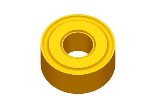
    ESTool RNMG Insert, Double-sided Round Negative Carbide Inserts?for medium and rough profiling.

    Feature:

    • Negative round common-type inserts with chipbreaker
    • For medium roughing applications

    ESTool RNMG Insert
    Insert shape Type ?Size (mm)
    L ΦI.C S Φd r
    Through slot RNMG120400 12.7 12.7 4.76 5.16


    Hot Sales Products:
    Carbide Grooving Inserts
    |
    Cast Iron Inserts
    |
    Milling inserts
    |
    Cermet Inserts
    |
    DNMG Insert
    |
    APKT Insert


    The Carbide Inserts Website: https://www.estoolcarbide.com/indexable-inserts/cnmg-insert/

    CCMW Insert, ISO 80° Positive Rhombic Indexable Turning Inserts

    ESTool SCMT Insert

    Description:

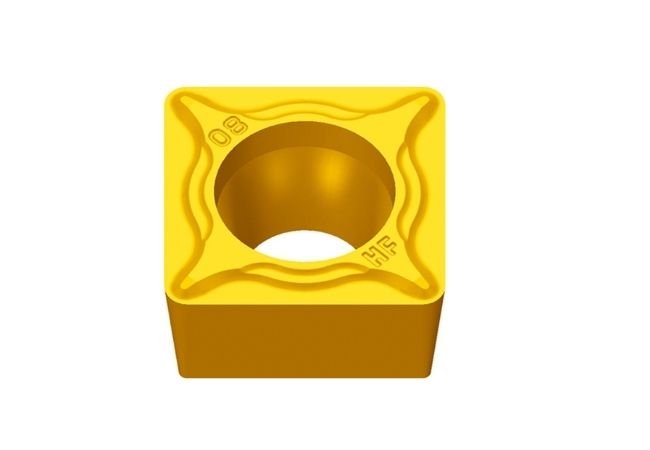
    ESTool SCMT Insert, 90° Square Indexable Carbide Turning Insert.?7° positive flank inserts for semi-finishing and finish turning. Chip breaking in moderate feed range. Positive rake, low cutting forces. Our general-purpose grade is designed to cut most materials including?stainless steels, mild steel, brass, bronze, aluminium and cast iron.

    Feature:

    • 90° Square insert
    • Single sided
    • Positive rake
    • 7° side clearance
    • Low cutting forces


    ESTool SCMT Insert
    HF
    Insert shape ?Type ?Size (mm)
    L ΦI.C S Φd r
    HF? Finishing SCMT09T302-HF 9.525 9.525 3.97 4.4 0.2
    SCMT09T304-HF 9.525 9.525 3.97 4.4 0.4
    SCMT09T308-HF 9.525 9.525 3.97 4.4 0.8
    EF
    Insert shape ?Type ?Size (mm)
    L ΦI.C S Φd r
    EF Finishing SCMT09T302-EF 9.525 9.525 3.97 4.4 0.2
    SCMT09T304-EF 9.525 9.525 3.97 4.4 0.4
    SCMT09T308-EF 9.525 9.525 3.97 4.4 0.8
    HM
    Insert shape ?Type ?Size (mm)
    L ΦI.C S Φd r
    HM? Semi-finishing SCMT09T304-HM 9.525 9.525 3.97 4.4 0.4
    SCMT09T308-HM 9.525 9.525 3.97 4.4 0.8
    SCMT120404-HM 12.7 12.7 4.76 5.56 0.4
    SCMT120408-HM 12.7 12.7 4.76 5.56 0.8
    SCMT120412-HM 12.7 12.7 4.76 5.56 1.2
    EM
    Insert shape ?Type ?Size (mm)
    L ΦI.C S Φd r
    EM Semi-finishing SCMT09T304-EM 9.525 9.525 3.97 4.4 0.4
    SCMT09T308-EM 9.525 9.525 3.97 4.4 0.8
    SCMT120404-EM 12.7 12.7 4.76 5.56 0.4
    SCMT120408-EM 12.7 12.7 4.76 5.56 0.8
    SCMT120412-EM 12.7 12.7 4.76 5.56 1.2
    HR
    Insert shape ?Type ?Size (mm)
    L ΦI.C S Φd r
    HR Roughing SCMT09T304-HR 9.525 9.525 3.97 4.4 0.4
    SCMT09T308-HR 9.525 9.525 3.97 4.4 0.8
    SCMT09T312-HR 9.525 9.525 3.97 4.4 1.2
    SCMT120404-HR 12.7 12.7 4.76 5.56 0.4
    SCMT120408-HR 12.7 12.7 4.76 5.56 0.8
    SCMT120412-HR 12.7 12.7 4.76 5.56 1.2
    Insert shape ?Type ?Size (mm)
    L ΦI.C S Φd r
    Through slot SCMT09T304 9.525 9.525 3.97 4.4 0.4
    SCMT120404 12.7 12.7 4.76 5.56 0.4
    SCMT120408 12.7 12.7 4.76 5.56 0.8
    Insert shape ?Type ?Size (mm)
    L ΦI.C S Φd r
    Slotless SCMW060204 6.35 6.35 2.38 2.8 0.4
    SCMW09T304 9.525 9.525 3.97 4.4 0.4
    SCMW09T308 9.525 9.525 3.97 4.4 0.8
    SCMW120408 12.7 12.7 4.76 5.56 0.8


    Hot Sales Products:
    Shoulder Milling Inserts
    |
    Carbide Grooving Inserts
    |
    Cemented Carbide Inserts
    |
    Cutting Tool Inserts
    |
    CNC Inserts


    The Carbide Inserts Website: https://www.estoolcarbide.com/product/hunan-estool-cemented-carbide-cnmg-tm-inserts-tools-for-steel-machining/

    RNMG Insert, Double sided Round Negative Carbide Inserts

    ESTool SNMG Insert

    Description:

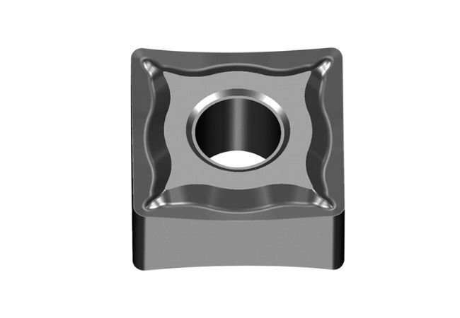
    ESTool SNMG Insert, special design reduces cratering. Used for carbon and alloy steel, stainless steel and high temperature alloys.

    Feature:

    • 90° Square insert
    • Double sided
    • Negative rake Rake
    • 9mm to 19mm cutting edges
    • Coating: CVD coated Al2O3/ TiAlN composite coating
    • Available in a range of radius for finishing, general purpose and rough turning

    ESTool SNMG Insert
    DF
    Insert shape ?Type ?Size (mm)
    L ΦI.C S Φd r
    ?DF? Finishing SNMG090304-DF 9.525 9.525 3.18 3.81 0.4
    SNMG090308-DF 9.525 9.525 3.18 3.81 0.8
    SNMG120404-DF 12.7 12.7 4.76 5.16 0.4
    SNMG120408-DF 12.7 12.7 4.76 5.16 0.8
    SNMG120412-DF 12.7 12.7 4.76 5.16 1.2
    EF
    Insert shape ?Type ?Size (mm)
    L ΦI.C S Φd r
    ?EF Finishing SNMG090304-EF 9.525 9.525 3.18 3.81 0.4
    SNMG090308-EF 9.525 9.525 3.18 3.81 0.8
    SNMG090312-EF 9.525 9.525 3.18 3.81 1.2
    SNMG120404-EF 12.7 12.7 4.76 5.16 0.4
    SNMG120408-EF 12.7 12.7 4.76 5.16 0.8
    SNMG120412-EF 12.7 12.7 4.76 5.16 1.2
    SNMG150608-EF 15.875 15.875 6.35 6.35 0.8
    SNMG150612-EF 15.875 15.875 6.35 6.35 1.2
    SF
    Insert shape ?Type ?Size (mm)
    L ΦI.C S Φd r
    SFFinishing SNMG090304-SF 9.525 9.525 3.18 3.81 0.4
    SNMG090308-SF 9.525 9.525 3.18 3.81 0.8
    SNMG120404-SF 12.7 12.7 4.76 5.16 0.4
    SNMG120408-SF 12.7 12.7 4.76 5.16 0.8
    SNMG120412-SF 12.7 12.7 4.76 5.16 1.2
    SNMG150608-SF 15.875 15.875 6.35 6.35 0.8
    PM
    Insert shape ?Type ?Size (mm)
    L ΦI.C S Φd r
    PM? Semi-finishing SNMG090304-PM 9.525 9.525 3.18 3.81 0.4
    SNMG090308-PM 9.525 9.525 3.18 3.81 0.8
    SNMG090312-PM 9.525 9.525 3.18 3.81 1.2
    SNMG120404-PM 12.7 12.7 4.76 5.16 0.4
    SNMG120408-PM 12.7 12.7 4.76 5.16 0.8
    SNMG120412-PM 12.7 12.7 4.76 5.16 1.2
    SNMG120416-PM 12.7 12.7 4.76 5.16 1.6
    SNMG150608-PM 15.875 15.875 6.35 6.35 0.8
    SNMG150612-PM 15.875 15.875 6.35 6.35 1.2
    SNMG190616-PM 19.05 19.05 6.35 7.94 1.6
    DM
    Insert shape ?Type ?Size (mm)
    L ΦI.C S Φd r
    DM? Semi-finishing SNMG090304-DM 9.525 9.525 3.18 3.81 0.4
    SNMG090308-DM 9.525 9.525 3.18 3.81 0.8
    SNMG120404-DM 12.7 12.7 4.76 5.16 0.4
    SNMG120408-DM 12.7 12.7 4.76 5.16 0.8
    SNMG120412-DM 12.7 12.7 4.76 5.16 1.2
    SNMG120416-DM 12.7 12.7 4.76 5.16 1.6
    SNMG150608-DM 15.875 15.875 6.35 6.35 0.8
    SNMG150612-DM 15.875 15.875 6.35 6.35 1.2
    SNMG150616-DM 15.875 15.875 6.35 6.35 1.6
    SNMG190612-DM 19.05 19.05 6.35 7.94 1.2
    SNMG190616-DM 19.05 19.05 6.35 7.94 1.6
    EM
    Insert shape ?Type ?Size (mm)
    L ΦI.C S Φd r
    EM? Semi-finishing SNMG120404-EM 12.7 12.7 4.76 5.16 0.4
    SNMG120408-EM 12.7 12.7 4.76 5.16 0.8
    SNMG120412-EM 12.7 12.7 4.76 5.16 1.2
    SNMG120416-EM 12.7 12.7 4.76 5.16 1.6
    SNMG150612-EM 15.875 15.875 6.35 6.35 1.2
    SNMG150616-DM 15.875 15.875 6.35 6.35 1.6
    NM
    Insert shape ?Type ?Size (mm)
    L ΦI.C S Φd r
    NM? Semi-finishing SNMG120408-NM 12.7 12.7 4.76 5.16 0.8
    SNMG120412-NM 12.7 12.7 4.76 5.16 1.2
    DR
    Insert shape ?Type ?Size (mm)
    L ΦI.C S Φd r
    DR? Light load roughing SNMG120408-DR 12.7 12.7 4.76 5.16 0.8
    SNMG120412-DR 12.7 12.7 4.76 5.16 1.2
    SNMG120416-DR 12.7 12.7 4.76 5.16 1.6
    SNMG150608-DR 15.875 15.875 6.35 6.35 0.8
    SNMG150612-DR 15.875 15.875 6.35 6.35 1.2
    SNMG150616-DR 15.875 15.875 6.35 6.35 1.6
    SNMG150624-DR 15.875 15.875 6.35 6.35 2.4
    SNMG190612-DR 19.05 19.05 6.35 7.94 1.2
    SNMG190616-DR 19.05 19.05 6.35 7.94 1.6
    SNMG190624-DR 19.05 19.05 6.35 7.94 2.4
    Insert shape ?Type ?Size (mm)
    L ΦI.C S Φd r
    DR? Roughing SNMM120408-DR 12.7 12.7 4.76 5.16 0.8
    SNMM120412-DR 12.7 12.7 4.76 5.16 1.2
    SNMM120416-DR 12.7 12.7 4.76 5.16 1.6
    SNMM150608-DR 15.875 15.875 6.35 6.35 0.8
    SNMM150612-DR 15.875 15.875 6.35 6.35 1.2
    SNMM150616-DR 15.875 15.875 6.35 6.35 1.6
    SNMM190608-DR 19.05 19.05 6.35 7.94 0.8
    SNMM190612-DR 19.05 19.05 6.35 7.94 1.2
    SNMM190616-DR 19.05 19.05 6.35 7.94 1.6
    SNMM190624-DR 19.05 19.05 6.35 7.94 2.4
    SNMM250724-DR 25.4 25.4 7.94 9.12 2.4
    SNMM250924-DR 25.4 25.4 9.525 9.12 2.4
    LR
    Insert shape ?Type ?Size (mm)
    L ΦI.C S Φd r
    LR?Light load roughing SNMM120408-LR 12.9 12.7 4.76 5.16 0.8
    SNMM120412-LR 12.9 12.7 4.76 5.16 1.2
    SNMM120416-LR 12.9 12.7 4.76 5.16 1.6
    SNMM150612-LR 15.875 15.875 6.35 6.35 1.2
    SNMM150616-LR 15.875 15.875 6.35 6.35 1.6
    SNMM190612-LR 19.3 19.05 6.35 7.94 1.2
    SNMM190616-LR 19.3 19.05 6.35 7.94 1.6
    SNMM190624-LR 19.3 19.05 6.35 7.94 2.4
    SNMM250924-LR 25.79 25.4 9.525 9.12 2.4
    ER
    Insert shape ?Type ?Size (mm)
    L ΦI.C S Φd r
    ER Roughing SNMG120408-ER 12.7 12.7 4.76 5.16 0.8
    SNMG120412-ER 12.7 12.7 4.76 5.16 1.2
    SNMG150608-ER 15.875 15.875 6.35 6.35 0.8
    SNMG150612-ER 15.875 15.875 6.35 6.35 1.2
    SNMG190612-ER 19.05 19.05 6.35 7.94 1.2
    SNMG190616-ER 19.05 19.05 6.35 7.94 1.6
    ER Roughing SNMM250724-ER 25.4 25.4 7.94 9.12 2.4
    SNMM250732-ER 25.4 25.4 7.94 9.12 3.2
    SNMM250924-ER 25.4 25.4 9.525 9.12 2.4
    SNMM250932-ER 25.4 25.4 9.525 9.12 3.2
    SNR
    Insert shape ?Type ?Size (mm)
    L ΦI.C S Φd r
    SNR Roughing SNMG120408-SNR 12.7 12.7 4.76 5.16 0.8
    HDR
    ?Insert shape ?Type ?Size (mm)
    L ΦI.C S Φd r
    HDR Gravity cutting SNMM120408-HDR 12.7 12.7 4.76 5.16 0.8
    SNMM120412-HDR 12.7 12.7 4.76 5.16 1.2
    SNMM120416-HDR 12.7 12.7 4.76 5.16 1.6
    SNMM150608-HDR 15.875 15.875 6.35 6.35 0.8
    SNMM150612-HDR 15.875 15.875 6.35 6.35 1.2
    SNMM150616-HDR 15.875 15.875 6.35 6.35 1.6
    SNMM150624-HDR 15.875 15.875 6.35 6.35 2.4
    SNMM190608-HDR 19.05 19.05 6.35 7.94 0.8
    SNMM190612-HDR 19.05 19.05 6.35 7.94 1.2
    SNMM190616-HDR 19.05 19.05 6.35 7.94 1.6
    SNMM190624-HDR 19.05 19.05 6.35 7.94 2.4
    SNMM250724-HDR 25.4 25.4 7.94 9.12 2.4
    SNMM250924-HDR 25.4 25.4 9.525 9.12 2.4
    HPR
    Insert shape ?Type ?Size (mm)
    L ΦI.C S Φd r
    HPRGravity cutting SNMM190616-HPR 19.5 19.05 6.35 7.94 1.6
    SNMM250924-HPR 25.4 25.4 9.525 9.12 2.4
    Insert shape ?Type ?Size (mm)
    L ΦI.C S Φd r
    Through slot SNMG090304 9.525 9.525 3.18 3.81 0.4
    SNMG090308 9.525 9.525 3.18 3.81 0.8
    SNMG120404 12.7 12.7 4.76 5.16 0.4
    SNMG120408 12.7 12.7 4.76 5.16 0.8
    SNMG120412 12.7 12.7 4.76 5.16 1.2
    SNMG120416 12.7 12.7 4.76 5.16 1.6
    SNMG150608 15.875 15.875 6.35 6.35 0.8
    SNMG150612 15.875 15.875 6.35 6.35 1.2
    SNMG190612 19.05 19.05 6.35 7.94 1.2
    SNMG190616 19.05 19.05 6.35 7.94 1.6
    SNMG250724 25.4 25.4 7.94 9.12 2.4
    SNMG250924 25.4 25.4 9.525 9.12 2.4
    Through slot SNMM090304 9.525 9.525 3.18 3.81 0.4
    SNMM090308 9.525 9.525 3.18 3.81 0.8
    SNMM120408 12.7 12.7 4.76 5.16 0.8
    SNMM120412 12.7 12.7 4.76 5.16 1.2
    SNMM120416 12.7 12.7 4.76 5.16 1.6
    SNMM190608 19.05 19.05 6.35 7.94 0.8
    SNMM190612 19.05 19.05 6.35 7.94 1.2
    SNMM190616 19.05 19.05 6.35 7.94 1.6
    SNMM250724 25.4 25.4 7.94 9.12 2.4
    SNMM250924 25.4 25.4 9.525 9.12 2.4
    Insert shape ?Type ?Size (mm)
    L ΦI.C S Φd r
    Slotless SNMA090304 9.525 9.525 3.18 3.81 0.4
    SNMA090308 9.525 9.525 3.18 3.81 0.8
    SNMA120404 12.7 12.7 4.76 5.16 0.4
    SNMA120408 12.7 12.7 4.76 5.16 0.8
    SNMA120416 12.7 12.7 4.76 5.16 1.6
    SNMA150608 15.875 15.875 6.35 6.35 0.8
    SNMA150612 15.875 15.875 6.35 6.35 1.2
    SNMA190612 19.05 19.05 6.35 7.94 1.2
    SNMA190616 19.05 19.05 6.35 7.94 1.6
    Insert shape ?Type ?Size (mm)
    L ΦI.C S r
    Slotless SNGN090308 9.525 9.525 3.18 0.8
    SNGN120408 12.7 12.7 4.76 0.8
    SNGN150408 15.875 15.875 4.76 0.8
    SNGN190412 19.05 19.05 4.76 1.2
    SNUN090304 9.525 9.525 3.18 0.4
    SNUN090308 9.525 9.525 3.18 0.8
    SNUN120408 12.7 12.7 4.76 0.8
    SNUN120412 12.7 12.7 4.76 1.2
    SNUN150408 15.875 15.875 4.76 0.8
    SNUN150412 15.875 15.875 4.76 1.2
    SNUN190408 19.05 19.05 4.76 0.8
    SNUN190412 19.05 19.05 4.76 1.2
    SNUN190424 19.05 19.05 4.76 2.4
    SNUN250724 25.4 25.4 7.94 2.4
    SNUN250924 25.4 25.4 9.525 2.4

    Hot Sales Products:
    Deep Hole Drilling Inserts
    |
    Cast Iron Inserts
    |
    Cemented Carbide Inserts
    |
    Tungsten Carbide Inserts
    |
    Machining Inserts


    The Carbide Inserts Website: https://www.estoolcarbide.com/product/togt-deep-drilling-inserts-cnc-lathe-cutting-indexable-carbide-drill-insert-p-1207/

    CNMM Insert, Negative Rake CNMM Carbide Inserts_4

    ESTool DCGT Insert

    Description:

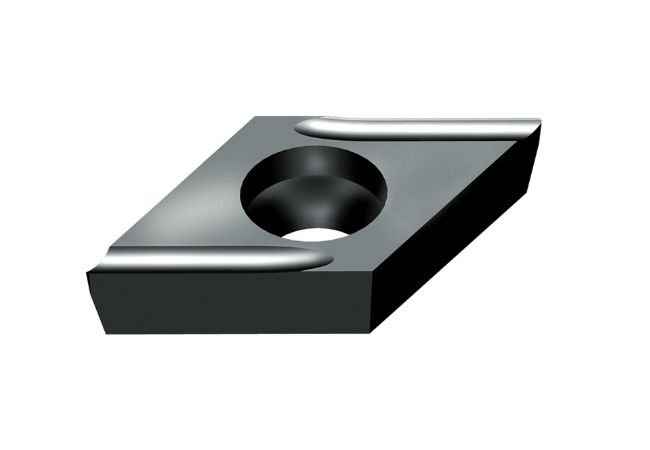
    ESTool DCGT Insert, 55° Rhombic Insert with 7° Positive Clearance For Finishing?Applications.

    Feature:

    • 55° Rhombic insert
    • Single sided
    • Positive rake
    • 7° side clearance
    • 7mm or 11mm cutting edges
    • Available in a range of radius for finishing, general purpose and rough turning

    ESTool DCGT Insert
    USF
    Insert shape ?Type ?Size (mm)
    L ΦI.C S Φd r
    USF Precision Machining DCGT0702005R-USF 7.8 6.35 2.38 2.8 0.05
    DCGT070201R-USF 7.8 6.35 2.38 2.8 0.1
    DCGT070202R-USF 7.8 6.35 2.38 2.8 0.2
    DCGT11T301R-USF 11.6 9.525 3.97 4.4 0.1
    DCGT11T302R-USF 11.6 9.525 3.97 4.4 0.2
    USF
    Insert shape ?Type ?Size (mm)
    L ΦI.C S Φd r
    USF Precision Machining DCGT0702005L-USF 7.8 6.35 2.38 2.8 0.05
    DCGT070201L-USF 7.8 6.35 2.38 2.8 0.1
    DCGT070202L-USF 7.8 6.35 2.38 2.8 0.2
    DCGT11T301L-USF 11.6 9.525 3.97 4.4 0.1
    DCGT11T302L-USF 11.6 9.525 3.97 4.4 0.2
    SF
    Insert shape ?Type ?Size (mm)
    L ΦI.C S Φd r
    SF Precision Machining DCGT070202-SF 7.8 6.35 2.38 2.8 0.2
    DCGT070204-SF 7.8 6.35 2.38 2.8 0.4
    DCGT070208-SF 7.8 6.35 2.38 2.8 0.8
    DCGT11T302-SF 11.6 9.525 3.97 4.4 0.2
    DCGT11T304-SF 11.6 9.525 3.97 4.4 0.4
    DCGT11T308-SF 11.6 9.525 3.97 4.4 0.8


    Hot Sales Products:
    Carbide Milling Inserts
    |
    Surface Milling Inserts
    |
    TCGT Insert
    |
    TNGG Insert
    |
    Lathe Inserts


    The Carbide Inserts Website: https://www.estoolcarbide.com/product/hunan-estool-cemented-carbide-cnmg-tm-inserts-tools-for-steel-machining/

    Skip to toolbar